An overview of designing and manufacturing 1.2379 cutting molds for thin steel sheet applications, focusing on durability, dimensional accuracy, and production efficiency.


In high-speed sheet metal production, cutting molds for thin steel sheets are exposed to continuous impact loading, abrasive wear, and tight cycle times. Any loss of cutting edge integrity or misalignment between the base and striker immediately translates into burr formation, dimensional drift, or cracked sheets.
For production lines running thousands of strokes per shift, mold failure is not a minor maintenance issue—it is a direct cause of unplanned downtime, scrap accumulation, and tool-change delays. In Cairo-based factories, where imported tooling can take weeks to replace, poor mold manufacturing quality often results in extended line stoppages and unstable production schedules.
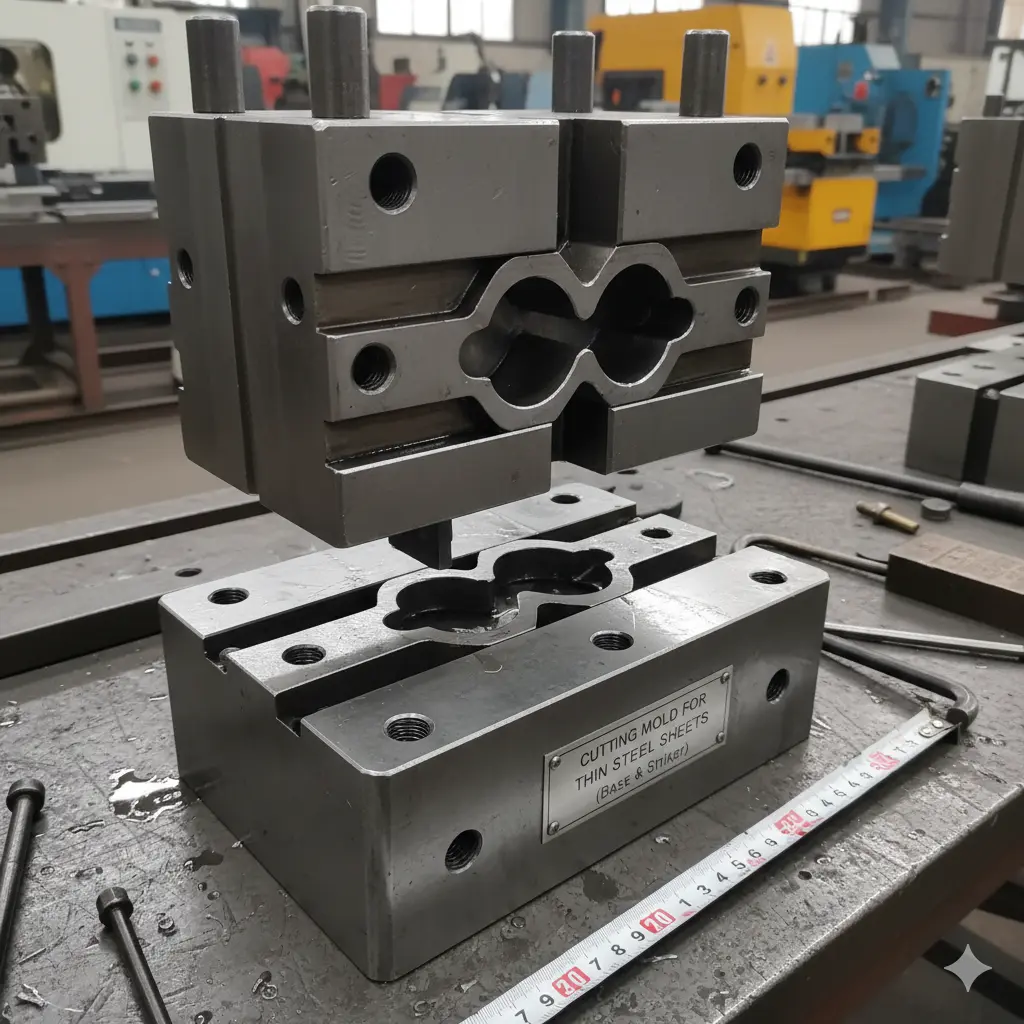
This is why the manufacturing discipline of a 1.2379 cutting mold for thin steel sheets (base & striker) must focus on wear resistance, dimensional stability after heat treatment, and repeatable cutting accuracy—not just initial sharpness.
A cutting mold for thin steel sheets consists of two critical working components:
These molds are commonly used in:
Poor clearance control or uneven hardness between the base and striker causes accelerated edge chipping, inconsistent shearing, and press overload. In real production environments, this leads to frequent regrinding cycles, press vibration, and premature failure of guide components.
1.2379 tool steel (X153CrMoV12 / D2 equivalent) is selected for cutting molds due to its high chromium content and carbide-rich microstructure.
Key engineering considerations include:
Typical hardness range after heat treatment:
Trade-offs:
For thin steel sheets, 1.2379 provides optimal edge life when clearance and surface finish are tightly controlled.
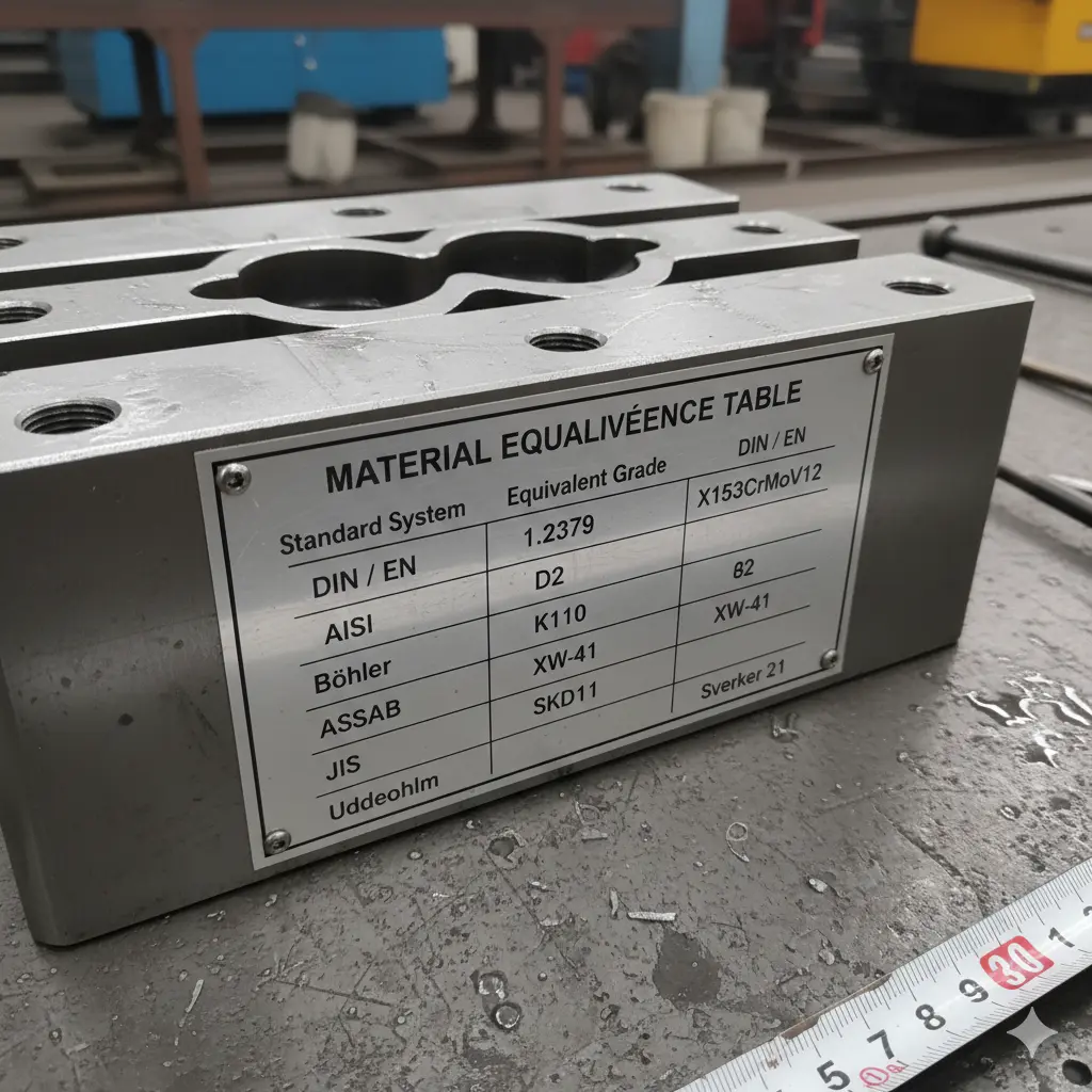
This equivalence is critical when sourcing raw material locally in Egypt while maintaining international tooling specifications.
Annealed 1.2379 tool steel is sourced with chemical composition verification to ensure carbide consistency. Poor-quality stock leads to uneven wear and unpredictable cracking.
Base and striker blanks are machined using rigid CNC setups. Machining allowances are left for post-heat-treatment grinding to compensate for distortion.
Mounting holes, ejector clearances, and alignment features are machined before heat treatment. Incorrect sequencing here results in positional errors after hardening.
Vacuum hardening minimizes oxidation and decarburization. Multiple tempering cycles stabilize the microstructure. Improper tempering causes edge chipping during early production.
Cutting edges, flatness surfaces, and mating interfaces are ground to final tolerances. Grinding burns or thermal cracks at this stage severely reduce tool life.
Clearance between base and striker is verified according to sheet thickness and material grade to ensure clean shearing.
Quality control directly defines mold lifespan and press stability.
Inspection includes:
Neglecting QC leads to uneven load distribution, press wear, and unpredictable maintenance intervals.
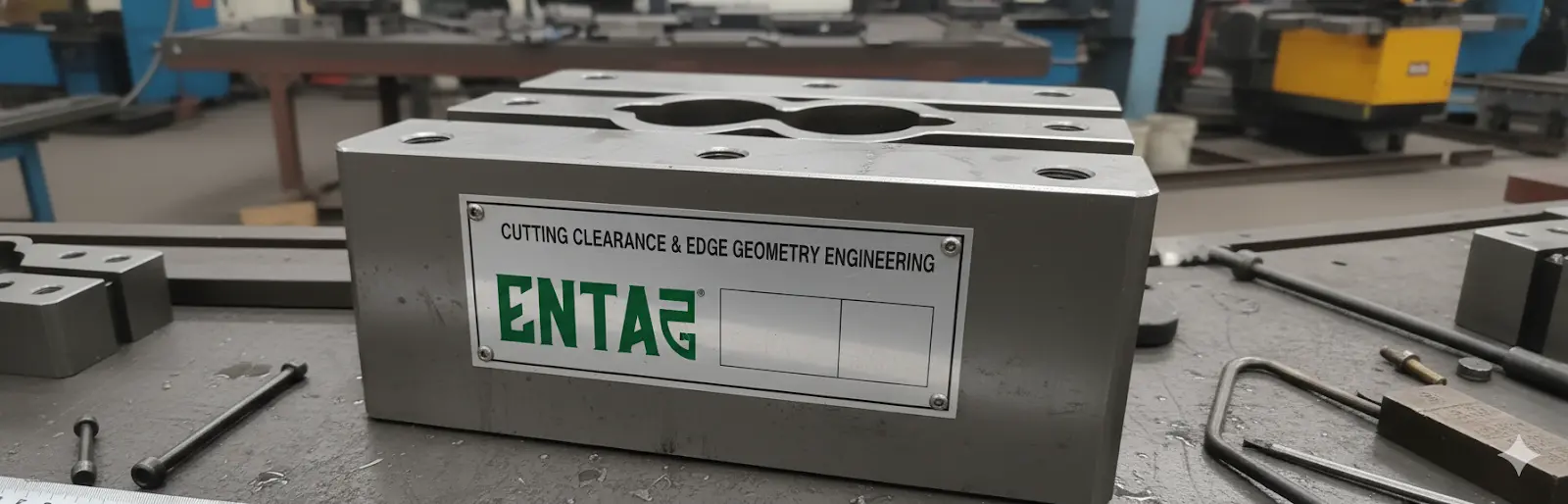
For a 1.2379 cutting mold for thin steel sheets (base & striker), cutting clearance and edge geometry are as critical as material selection. Even a properly hardened tool steel will fail prematurely if clearance is miscalculated.
In thin steel sheet cutting, clearance is typically defined as a percentage of sheet thickness per side. In production environments, incorrect clearance leads to immediate and measurable problems:
For thin carbon steel sheets, controlled clearance ensures:
Contrary to common assumptions, an extremely sharp edge is not always optimal for production:
Edge geometry must be finalized during grinding, not machining. Inconsistent edge finishing at this stage often results in uneven wear and early failure during ramp-up production.
Understanding failure modes is essential for maintenance planning and mold redesign. In real production environments, most cutting mold failures are not material-related but process-related.
Root Causes:
Operational Impact:
Root Causes:
Operational Impact:
Root Causes:
Operational Impact:
Root Causes:
Operational Impact:
Local manufacturing of cutting molds in Cairo allows faster response to wear issues, immediate dimensional adjustments, and reduced dependence on imported tooling with long lead times.
Egyptian manufacturers often face import delays for tooling that exceed production downtime tolerance. Cutting molds are maintenance-driven components, not one-time purchases. Rapid local production of 1.2379 cutting molds ensures production continuity, predictable maintenance planning, and controlled tooling costs.
A 1.2379 cutting mold for thin steel sheets (base & striker) is a critical production asset. Proper material selection, disciplined heat treatment, and strict inspection reduce total cost of ownership by extending tool life and stabilizing press performance. Manufacturing shortcuts always surface later as downtime and scrap.
Entag manufactures cutting molds, punches, dies, and wear components from 1.2379 and other tool steels.
It is optimized for thin to medium thickness sheets requiring high wear resistance.
Service life depends on sheet material and clearance but typically exceeds lower-alloy tool steels.
Yes, base and striker geometry are customized per press and application.
Yes, provided sufficient grinding allowance was designed initially.
Local manufacturing significantly reduces lead time compared to imported tooling.